Water Tank Installation And Commissioning: From Site Prep To First Fill
Planning Before the Tank Arrives
Review the general arrangement drawing line by line and fix the orientation of every nozzle, including inlet, overflow, vent, drain, gauge ports and conduit entries, relative to the incoming mains, the pump suction header and the access route. A nozzle that is thirty degrees out of place usually means the tank gets lifted twice.
Weight, support loads and the data the supplier needs
Give the supplier the working volume, the product density, the operating and test temperatures, the design pressure or vacuum, the support arrangement and the nozzle schedule. Ask for the shell thickness, the design code, the weld procedure and the intended test pressure with the offer. A tank quoted on a data sheet the vendor wrote himself is harder to compare than one quoted against a written duty.
Foundation, Support Type and Level Tolerance
| Support type | Typical use | Foundation requirement | Level tolerance |
|---|
| Concrete base ring or full slab | Most vertical tanks up to about ten metres diameter | Rated slab with compacted sub-base, or a plinth ring sized for the full footprint | Across the bearing surface within three millimetres |
| Concrete or steel saddles | Horizontal tanks, and vertical tanks on low saddles | Two or more isolated pads, each sized for the reaction at that support | Saddle tops level within two millimetres along the length and square to the tank axis |
| Skirt support | Vertical tanks needing a high working volume on site | Reinforced concrete ring beam, anchored to suit the moment reaction | Skirt base plumb within five millimetres over the height |
| Legs or stools | Small tanks, or tanks raised for gravity drainage | Individual pads under each leg, level and in the same plane | Each leg pad within two millimetres of the others |
Anchoring and the details that decide whether the tank stays square
Set the tank on shims and packs, never on loose packer or on steel plate bridging soft ground. Check plumb with a level on the shell, not on the nozzle flanges, and re-check after the anchors are set, because tightening can pull a shell out of shape. Hold-down anchors should be sized for the overturning and uplift case, not only for the empty weight. If the tank has a plastic or coated lining, isolate the anchor plates with insulating washers so the coating is not crushed.
Delivery, Handling and Site Storage
Inspect the tank the moment it arrives, before the vehicle leaves. Photograph the shell, check the welds and the coating, and compare the damage against the delivery note. Typical transit damage is a dented shell around a lifting lug, a twisted stiffener ring, a cracked or missing access hatch cover, and a sheared bolt on a flanged nozzle. Record everything with photographs and have it noted on the delivery receipt before signing.
Mechanical Installation and Piping Connections
Assemble in the order that gives you access. Start with the base frame or supports, then the shell on its support, then internal items, then the roof, then platforms and ladders. Do not force shell sections together to close a gap. Misalignment that is pulled tight shows up later as flange leakage, distorted openings and a tank that is permanently out of round.
Gaskets, flanges and bolt control
Use the gasket material specified for the product and the temperature, and replace every gasket that has been re-used or distorted. Bolts are tightened in a star pattern to a defined torque, not by feel, and flanges are checked for parallel alignment before the bolts are fully tensioned. A flange bolted tight against a cocked face will leak in service, and the leak usually shows up as a small weep that is easy to ignore.
Electrical, Bonding and Access Safety
Tank shells should be bonded together and to the site earth, and connected to the earthing system through a dedicated earth pit that is tested for continuity and for earth resistance against the design value. Flexible bonding straps are needed across any insulating joint, including gasket-lined flanges that interrupt the metallic path.
Commissioning Sequence
Commissioning should follow a fixed order: clean, flush, test, disinfect if the duty is potable, then fill. Jumping straight to filling carries debris, weld slag and cutting oil into the system and onto the internals of the pump and the downstream treatment plant.
Cleaning, flushing, testing and the first fill
| Step | Action | Acceptance criterion |
|---|
| 1 | Internal inspection and debris removal; check baffles, screens and internals are secured | Clean and dry, with no loose items or tools left inside |
| 2 | Flush with clean water through the inlet, drain and overflow in turn | Outlet water runs clear, with no visible solids or oil film |
| 3 | Leak test all flanged and threaded joints at operating pressure | No visible leakage, with joint test records available |
| 4 | Hydrostatic test of assembled or site-welded parts when the shell cannot be tested at the works | Test pressure held for the specified duration, with no pressure drop and no visible distortion |
| 5 | Disinfection for potable duty, using the approved chemical, contact time and flushing sequence | Disinfection certificate and post-flush sample results |
| 6 | Fill slowly, purging air from the top vent, comparing the level instrument against a manual reading | Instrument reads within the stated error of the manual level |
| 7 | First circulation or turnover of the full volume | Full turnover completed with no turbidity or debris at the outlet |
Handover Documentation and the First 90 Days
The handover pack is what protects both parties afterwards. It should include the general arrangement and nozzle schedule, the material certificates for the shell and the internals, the coating or lining record with thickness readings, the welding procedure specifications and welder qualifications for any site welding, all test records, the operation and maintenance manual, the spare parts list, and the warranty terms as documented in the contract. Keep the documents that accompany the equipment rather than leaving them on site.
| Common installation mistake | What goes wrong | How to avoid it |
|---|
| Tank set on an unlevel or undersized foundation | Shell distortion, uneven gasket compression, persistent joint leaks | Check level and plumb on the shell, and re-check after anchoring |
| Nozzles rotated to suit the drawing instead of the site | Re-lifting, extra cost, damaged coating | Mark nozzle orientation on site before fabrication |
| Pipework supported off the tank nozzles | Leakage at flanges and nozzle distortion | Support pipework on stanchions and use flexible connectors |
| Bolts over-tightened on unequal gasket compression | Cracked flange, gasket blow-out, bolt fatigue | Star pattern over several passes, verifying an even gap |
| Tank filled before flushing and inspection | Debris carried into the pump and downstream plant | Clean, flush and test before the first fill |
| Access ladder and platform missing or unguarded | Falls during routine inspection | Complete access and guarding before handover |
Frequently Asked Questions
How long does installation take?
For a single vertical tank of moderate size with all connections made on site, a working installation typically runs from a few days to two weeks, including foundation curing, delivery, mechanical completion, electrical work and commissioning. It takes longer if the foundation has to be built from scratch, if the tank is large enough to need a crane on site for more than a day, or if disinfection and water quality sampling are required.
Do I need a concrete foundation, and can the tank be installed indoors?
A concrete foundation is the normal and preferred arrangement because it spreads the load, keeps the shell level and provides a clean, washable base. Tanks can be installed indoors in a plant room or basement, provided the space has adequate headroom for the shell and roof hatch, a delivery and lifting route, ventilation so the tank can be drained and cleaned, and enough floor loading capacity. Indoor installation also brings the overflow and vent into the room ventilation design and usually requires a bunded or contained area.
How do I test the tank for leaks?
Test in stages. Check flanged and threaded joints individually under operating pressure, and confirm the shell joints visually and, where required, by hydrostatic test at the works with a test certificate. For a site-assembled or site-welded tank, carry out a full hydrostatic test at the specified pressure and hold time and check for permanent distortion of the shell and roof. For a sealed vessel, a low-pressure vacuum or smoke test on the roof and hatch seals can find leaks that water would take time to reveal.
What maintenance is needed after commissioning?
Establish a routine that includes an external visual inspection of the shell, coating and welds, checking the level instrument against a manual reading, checking the bund and drain path, testing earth continuity, servicing the overflow and vent so they stay unblocked, and inspecting gaskets and seals at flanged connections. Keep the interior clean, monitor water quality for potable duty, and record all readings and repairs so trends are visible rather than a single failed inspection.

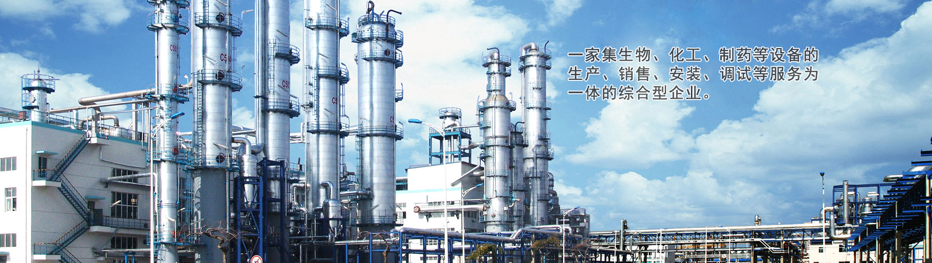
 Storage tanks and tower series